Suitability-for-Service Evaluations for Pressure Vessels and Storage Tanks
Author: Brian R. Macejko, Group Head, Consulting Engineer II
Note: The following article is an updated version of a 2016 Industry Insights article.
The Occupational Safety and Health Administration (OSHA) requires owner-operators to maintain essential documentation authenticating adequate design and maintenance of pressure vessels and storage tanks. Unfortunately, it is not uncommon to find equipment operating in industry with minimal or no documentation. This has become even more common in recent years with the re-purposing of assets for use in new facilities.
Suitability-for-service (SFS) is the process of performing inspection and engineering to obtain OSHA compliance for fixed equipment lacking documentation. E2G | The Equity Engineering Group, Inc. has completed thousands of SFS evaluations, giving us the experience and capability to provide the most cost-effective solution for owner-operators.
WHAT EQUIPMENT REQUIRES SFS EVALUATION?
An SFS evaluation is typically required for any of the following scenarios:
- Equipment lacking any component of the OSHA-required nameplate, records, and stamping (NRS) documentation. Records would include drawings, manufacturer’s data reports, inspection reports, etc. Stamping implies validation of design via a code stamp.
- Equipment that was repaired or altered post-construction without proper NRS documentation.
- Equipment built to a code or standard that is not consistent with the latest industry code or standard requirements. This includes equipment built to a previous edition of a code if the latest industry code or standard has supplemental or more stringent requirements beyond those implemented in the original design of the equipment. For example:
- The 1987 addenda to the 1986 edition of ASME Section VIII, Division 1 introduced new requirements for the evaluation of susceptibility to brittle fracture.
- The 1989 edition of ASME Section II Part D included a reduction in the allowable stress criteria for low-chrome alloys at elevated temperatures due to concern for potential creep damage.
OSHA REGULATIONS AND INTERPRETATIONS
Process safety management requirements are outlined in the OSHA 1910 standards. For equipment operating in hazardous service, it is mandatory that an employer document that the equipment complies with recognized and generally accepted good engineering practices (RAGAGEP). OSHA interprets the statement “built in accordance with the ASME Boiler and Pressure Vessel Code” to require that employers use pressure vessels that at least conform with the requirements of the code, including the proper maintenance and display of NRS. OSHA interpretation 2006-07/17/2006 Pressure vessels used at oil and gas extraction/production facilities and applicability of 29 CFR 1910.106 states that in cases where traceability of the required NRS documentation is not possible, OSHA will treat as a de minimis violation provided:
- Employer can demonstrate that it has taken reasonable steps to obtain or retain the required NRS, and
- Employer verifies the fitness-for-operations integrity of the vessels by utilizing the procedure contained in API 510
Furthermore, OSHA states that previous editions of a current code or standard (e.g., 1972 edition of ASME Section VIII, Division 1) are considered to be “a code or standard no longer in general use.” Therefore, the employer shall “assure that the equipment can continue to function in a safe manner” with regards to any differences in the original code of construction compared to the latest edition of the code or standard.
FIXED EQUIPMENT LIFE-CYCLE MANAGEMENT
Figure 1 outlines the general life cycle for fixed equipment operating in a refining or process environment. An SFS evaluation is intended to validate equipment design and provide documentation of baseline thickness inspection to therefore enable future monitoring of the equipment mechanical integrity. Without fulfilling these steps, an owner-operator cannot effectively manage their equipment.

INDUSTRY GUIDANCE
The following section includes a summary of pertinent industry guidance regarding evaluation of equipment lacking documentation. Unfortunately, the guidance available does not cover all situations encountered, and many times the recommended minimum baseline assumptions result in overly conservative results. Knowing when and how to justify less conservative assumptions for the evaluations can be critical in determining whether alteration or replacement can be avoided.
API 510 (10th Edition)
API 510 Section 7.7 Evaluation of Existing Equipment with Minimal Documentation is recognized by OSHA interpretations as the acceptable means to determine suitability of pressure vessels. A more detailed summary of the API 510 procedure will be provided.
NBIC (2019 Edition)
National Board Inspection Code (NBIC) Part 3 Section 1.2(b) states, “If the pressure-retaining item was not constructed to a construction code or standard,…repairs or alterations shall conform, insofar as possible, to the edition of the construction standard or specification most applicable to the work.”
API 653 (5th Edition)
API 653 Paragraph 13.1.2 Tanks Without Nameplates states, “If information required to complete the nameplate as required by the as-built standard is not available, an ‘Assessment Nameplate’ may be attached under the direction of the Authorized Inspector, provided a suitability for service assessment is performed per API 653, Sections 4 and 5.” Section 4 of API 653 provides details on how to evaluate a tank roof, shell courses, floor, and foundation. Section 5 includes considerations to prevent brittle fracture.
SFS PROCESS OVERVIEW
The industry-accepted API 510 procedure for SFS is a 6-step process. A brief overview of each step is summarized below.
Step 1 – Inspect
Sufficient inspection of the equipment, including various nondestructive examination (NDE) methods and visual examination, is required to determine the general condition of each component. The extent of inspection completed for an SFS evaluation is not intended to identify damage or replace API 510, API 653, or API 581 routine inspections. There is an expectation that all equipment must be included in a supplemental routine inspection program consistent with industry codes and standards, and the inspection tasks must be deemed appropriate for the potential damage mechanisms to which the equipment or components may be susceptible to.
At a minimum, ultrasonic examination (UT) shall be completed on each equipment component (including each shell course, heads, floors, roofs, transitions, nozzles, reinforcement pads, etc.). To guide the inspection efforts, E2G will recommend how many inspection readings are required for each component as well as the critical locations for UT inspection.
Step 2 – Prepare Drawings
Detailed drawings must be prepared with sufficient details and dimensions to perform the necessary SFS calculations.
To assist with the dimensional information gathering efforts, E2G provides standard data collection sheets for typical components and equipment (Figure 2).
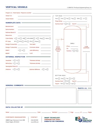

Figure 2 – Example of E2G’s SFS Data Collection Sheets
Step 3 – Define Design Parameters
All applicable design parameters must be defined by the owner-operator such that loading conditions are analyzed appropriately. Typical design parameters include:
- The maximum internal design pressure required considering all operating and upset conditions. Consider pressure safety valve (PSV) set points and relief capacity.
- The maximum design temperature required considering all operating and upset conditions.
- External pressure shall be considered where applicable (including steam-out conditions, etc.).
- The critical exposure temperature (CET) as defined in Part 3 of API 579 considering all ambient, operating, and upset conditions to which the equipment or component may be exposed.
- Details (magnitude and frequency) regarding any cyclic loading (pressure, fill height, and/or temperature).
- The maximum liquid fill height(s) and content specific gravity.
Step 4 – Perform Design Calculations
Calculations should be completed by an engineer competent in equipment design. Typically, pressure vessels are evaluated using ASME Section VIII, Division 1 and atmospheric storage tanks are evaluated using API 653 and API 650. However, there are times when the principles, procedures, and guidance from other codes and standards, particularly API 579 or ASME Section VIII, Division 2, can be effectively utilized to justify operation.
Loading
Calculations must be completed to assess all pertinent loading. It is imperative that supplemental loading due to weight, wind, seismic, and snow are included in the evaluations when necessary. Evaluations completed considering only pressure loading may prove non-conservative at times. Industry guidance on how and when to include these other loading conditions is not explicit for most situations. Therefore, it is important to document the methodology and assumptions implemented in the evaluation, including the screening criteria used to neglect certain loads.
Material Properties
API 510 and API 653 provide guidance on initial base input assumptions for materials (particularly, allowable stress and impact test exemption curves) when documentation is not available. However, these assumptions are conservative and can subsequently become very limiting. Additional inspection and engineering may be utilized to justify less conservative material properties.
Weld Joint Efficiency
API 510 would dictate that if a component weld joint efficiency and extent of radiographic examination (RT) are unknown, the following assumptions should be used:
- 0.7 for Type No. (1) butt welds
- 0.65 for Type No. (2) butt welds
- 0.85 for seamless shells, heads, and nozzles
Additional inspection and engineering may be utilized to justify a higher weld joint efficiency. However, it should be noted that additional examination of welds may result in the need for an FFS evaluation or repairs if defects are found.
Additional Engineering Considerations
The following is a list of additional items that may require engineering consideration:
- Inclusion of an appropriate future corrosion allowance (FCA)
- Treatment of non-standard components (such as nozzles in header boxes, burst tested components, etc.)
- Structural thickness limits for components
- Considerations for potential nozzle external loadings due to attached piping
- Assumptions pertaining to gasket material properties and dimensions for flanged joints
- Fatigue screening criteria for evaluation of components or equipment that operate in a cyclic environment (numerous pressure, temperature, or liquid level fluctuations)
Step 5 – Attach Nameplate
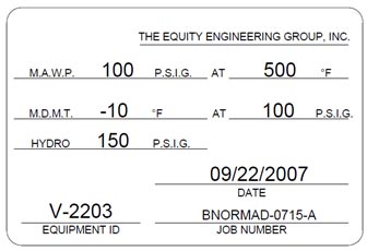
In order to align a permanent record of the SFS evaluation results to the equipment, a nameplate must be installed. Both API 510 and API 653 provide explicit instructions regarding the information that must be included on the equipment nameplate.
Step 6 – Perform Hydrostatic Pressure Test
The final step in the API 510 procedure for SFS is to perform a hydrostatic pressure test in accordance with the construction code used in the SFS calculations. Care should be taken to ensure metal temperature at the time of the test is adequate to minimize the potential for brittle fracture.
API 653 permits the use of FFS and supplemental NDE as an alternative to a hydrotest. The FFS evaluation would include a detailed fracture mechanics assessment to gain a better understanding of sensitivity to weld defects and crack-like flaws, particularly at the critical floor-to-shell weld joint.
ALTERNATIVES TO SFS
Aside from completing an SFS evaluation, the only alternative to achieve OSHA compliance for equipment lacking documentation is replacement. In the short term, the owner-operator would have to either shut down the equipment until the replacement can be obtained or else continue to operate (with uncertainty regarding suitability and knowing equipment is out of compliance) until the replacement can be installed. There would be added liability and risk associated with continued operation.
Typically, the installation cost of a new equipment item is 4 to 5 times the cost of the asset itself; therefore, even relatively low-cost vessels can result in significant cost. Additionally, inspection would still be required prior to replacement in order to obtain the dimensions and details necessary for requisition. Consequently, an SFS evaluation tends to be the fastest and most cost-effective means to achieve OSHA compliance for almost all scenarios.
LARGE-SCALE PROJECT CONSIDERATIONS
If numerous equipment items requiring SFS exist at a particular facility, it is beneficial to complete all the evaluations together as a single “large-scale” project to expedite results; ensure consistency with methodologies, procedures, and assumptions; and minimize cost by taking advantage of the efficiencies gained through focused inspection and engineering personnel assigned to the project.
Large-scale projects can also present several challenges. Experienced project management, regular communication, and clearly defined procedures and actions are required. For large-scale projects, E2G typically develops a project protocol document to ensure consistency and maximize efficiency. The protocol document is crucial for successful execution of the project and provides guidance such as:
- Roles and responsibilities for the various parties involved in the project (inspection, owner-operator, analysts, etc.)
- Data requirements
- Technical methodology
- Engineering assumptions
- Screening criteria for filtering equipment and applicable loading considerations
- Template for consistent presentation and documentation of results
- Reference materials
To allow for consistent and transparent equipment and status tracking, an electronic workflow management system may be employed. This system allows all parties involved in the project to have access to live updates on status, open action items, and final disposition for each equipment evaluation. Additionally, it allows for electronic tracking of the project workflow (waiting on data, ready for analysis, ready for review, draft issued, issued as final).
ADDITIONAL CONSIDERATIONS OR FOLLOW-UP ACTIVITIES
Minimum Required Thickness Calculations
Although not a requirement of an SFS evaluation, it is typical to perform code minimum required thickness (tmin) calculations for the various equipment components (shells, heads, nozzles, etc.) to facilitate future inspection monitoring and mechanical integrity management. If component tmin calculations are performed, engineering guidance should be documented regarding the various loading conditions analyzed as well as the structural tmin limits implemented (such as API 579 limits, ASME Section VIII, Division 1 UG-16 limits, nozzle structural limits, etc.). As previously noted, there are many scenarios where it is non-conservative to only consider internal pressure loading when establishing a tmin value.
Damage Mechanism Review and Inspection Planning
Upon completion of an SFS evaluation to validate equipment design rating, it is recommended that a formal damage mechanism review is completed to subsequently identify and optimize adequate inspection tasks and future inspection intervals. A risk-based inspection (RBI) evaluation may be advisable.
Pressure Relief Studies
Pressure relief requirements for equipment and systems cannot be established or verified unless the equipment ratings are validated. Once an SFS evaluation is complete, the relief protection for the asset or system may require re-evaluation.
FFS vs. SFS
As seen in Figure 1, fitness-for-service (FFS) is used to make run, repair, or replace decisions for equipment that is found to contain flaws or damage. An FFS assessment can also be used to provide guidance on an inspection interval through determination of remaining life. API 579 is the industry-recognized standard for FFS.
An SFS evaluation can be likened to “reverse engineering” an asset using guidance, principles, and procedures from design codes (such as ASME Section VIII, Division 1) and API 579. However, an SFS evaluation is typically not intended to qualify equipment for a specific damage mechanism. Rather, the purpose of the SFS is to define a rating for a piece of equipment so that subsequent inspection plans (API 510 or API 581) can be developed for all applicable damage mechanisms. Based on future inspection findings, an FFS may consequently be required if damage is found.
Jurisdictional Requirements
The owner-operator should always consult with their local jurisdiction to determine whether there are any additional requirements and/or limitations associated with SFS assessments within the location where the equipment resides.
E2G EXPERIENCE
E2G has performed thousands of SFS assessments, including multiple large-scale projects. We have completed SFS evaluations for equipment operating in refineries, up-stream exploration facilities, gas processing and mid-stream facilities, pipeline stations, chemical plants, fertilizer plants, and a variety of other industries. We routinely evaluate equipment of varying complexity from small low-pressure ancillary vessels to critical high-pressure reactors. Field data collection sheets have already been generated to accommodate almost any equipment item, and we are constantly improving and updating our SFS engineering protocol documents and workflow systems as new situations are encountered or when improvements and efficiencies are identified.
As an additional deliverable to large-scale projects, E2G can offer the owner-operator a fully populated SagePlus™ database to facilitate future mechanical integrity management in the event a rerate, repair, alteration, or FFS evaluation becomes necessary. SagePlus™ helps an analyst expedite the FFS evaluation process to assess damage due to wall loss (general metal loss, local thin area, or pitting), cracking, distortion, dents or gouges, creep, hydrogen damage, laminations, fire damage, or susceptibility to brittle fracture. As shown in Figure 4, the software includes sketches and detailed descriptions of input variables to facilitate use by analysts.

Figure 4 – SagePlus™
SUMMARY
An SFS evaluation is the fastest and most cost-effective process for achieving OSHA compliance for equipment lacking documentation. Knowing when and how to justify less conservative assumptions for the evaluations can be critical in determining whether repair, alteration, or replacement can be avoided. E2G is an expert engineering service provider with the technical knowledge and practical experience to know what is required and the best way to get there. E2G can complete the SFS evaluations in the most efficient and effective way possible and offer a full suite of additional services and products to facilitate the full life-cycle management of fixed equipment.
For more information, please fill in the form below: