Author: Katelyn J. Gustoff, Consulting Engineer I
A Discussion of the Opportunities and Benefits of the API 579-1/ASME FFS-1 Technology
Introduction
The identification of damage is often an inevitable part of the life cycle of industry fixed equipment. Aboveground storage tanks (ASTs) take no exception to this rule as they can accumulate a wide range of damage—damage that is both intended for in the initial design as well as unanticipated due to service, operational upsets, environment, etc. If unanticipated damage is discovered, repair or replacement of the affected components may be the initial reaction; however, a more favorable alternative could be a fitness-for-service (FFS) assessment to qualify continued service in the damaged condition. FFS is a recognized industry practice for assessing equipment mechanical integrity and can often be used to extend service life while minimizing downtime and avoiding costly repairs. This article will review the application of the API 579-1/ASME FFS-1 (API 579) FFS standard for common damage found in ASTs. Several case studies will be provided to illustrate how FFS techniques can be used to make run-repair-replace decisions, determine remaining life, and, when repairs are unavoidable, limit the extent of repairs needed.
Application of API 579 to ASTs
In-service standards such as API 653, Tank Inspection, Repair, Alteration, and Reconstruction provide minimum requirements for maintaining the integrity of ASTs after they have been placed in service. API 653 offers guidance on repair and damage evaluation but does not contain a comprehensive set of rules to cover assessment of all potential damage types. Per paragraph 1.1.6 of API 653, the use of the API 579 FFS technology is permitted when API 653 does not provide specific evaluation procedures or when API 653 otherwise explicitly allows it. Likewise, paragraph 1.2.2 of API 579 references the use of the FFS assessment procedures for ASTs designed to API 650, Welded Tanks for Oil Storage and API 620, Design and Construction of Large, Welded, Low-Pressure Storage Tanks as well as other recognized codes and standards. Thus, a mutual relationship exists between the API 653 and API 579 standards to permit the use of detailed FFS assessment in a variety of situations commonly associated with ASTs; several of these damage conditions are discussed in more detail below.
Shell Distortion
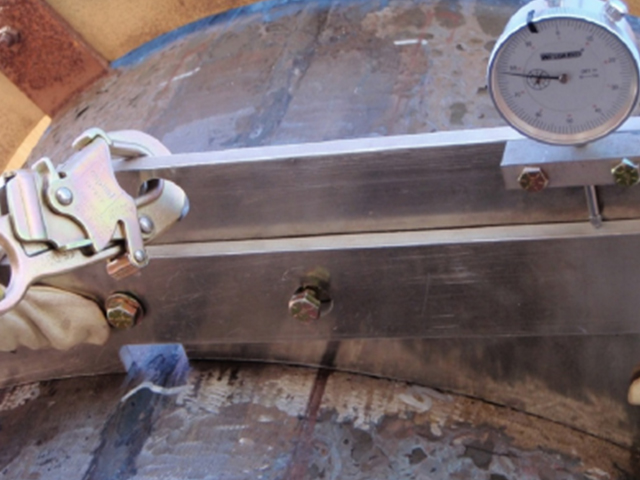
Given the large size and flexible nature of AST designs, damage in the form of shell distortions is a relatively common occurrence. Shell distortion may be local (e.g., bulge, flat spots, peaking/banding) or can present as more widespread (e.g., out-of-roundness, plumbness, global buckling). Shell distortion damage can be caused by a variety of conditions such as foundation settlement, operational upsets, high wind or seismic events, and inadequate repair techniques. Per paragraph 4.3.5.3 of API 653, shell distortions “shall be evaluated on an individual basis to determine if specific conditions are considered acceptable for continuing tank service and/or the extent of corrective action.” Other than general tolerances on tank roundness, weld misalignment, and foundation settlement, guidance on distortion evaluation is not explicitly provided in API 653; thus, API 579 Part 8 “Assessment of Weld Misalignment and Shell Distortions” can be applied for FFS evaluation of AST shell distortion damage. The FFS assessment procedures in API 579 are organized by flaw type and/or damage mechanism. Three levels of assessment are offered for each flaw or damage type: Level 1 is the most conservative but easiest to implement and Level 3 is the most detailed evaluation that produces the most precise results. Additionally, each level of assessment has certain required data inputs and limits of applicability. This is important because the API 579 Part 8 Level 1 and Level 2 assessment methods are often limited in their applicability to ASTs due to the complex geometry (i.e., multiple curvatures) that typically characterize distortion damage on tank shells. Thus, in many instances, the rigor of a Level 3 FFS assessment using finite element analysis (FEA) is required to evaluate an AST subject to distortion damage. Such an assessment requires accurate measurement of the shell distortion, which is most commonly collected using a laser scan survey. A brief case study of a Level 3 FFS assessment of an AST subject to shell distortion damage is provided.
Case Study – Level 3 Shell Distortion
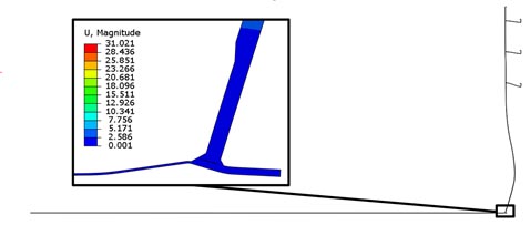
Routine inspection was performed on a 1950s carbon-steel AST measuring 60 feet (18 m) in diameter and 48-feet (14.6 m) tall. Results of the inspection identified shell distortions exceeding the API 653 radii and plumbness tolerances. The distortion was believed to be a result of differential shell settlement that was not expected to progress based on the vintage of the tank. Due to the complex geometry of the distortion damage, an API 579 Level 3 FFS assessment was performed in accordance with Part 8 using FEA techniques aligning with Annex 2D. The shell distortions were collected using 3D laser scan technology, and post-processed measurements were explicitly mapped onto the FEA model of the corroded AST geometry. Non-linear elastic-plastic analysis was performed to assess the AST’s fitness for continued service when subject to required load combinations of weight, product fill, wind, and seismic loads. Applicable failure criteria such as plastic collapse, buckling, and local strain accumulation were investigated.
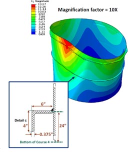
Initial results indicated the AST satisfied the required plastic collapse and local strain criteria with full product fill height considered; however, wind and seismic loading highlighted risk for buckling instability under the required load cases. Since the AST is most susceptible to buckling under high wind loads when empty, an iterative assessment was performed to determine the minimum fill height under design wind speeds (>100 mph/>160 km) and the maximum permissible wind speed considering an empty tank. The result was a recommended operational control of a minimum fill height of 66% full in the event of wind velocity exceeding 70 mph (112 km/h). This control was ultimately determined to be problematic for the tank operations team, so a wind girder was instead designed, evaluated, and installed as an alternate form of mitigation. Meanwhile, the seismic results were further addressed through a comparative assessment of the AST in the nominal, un-damaged condition versus the corroded, distorted condition. This comparative assessment concluded that the stability of the tank under seismic loading was not significantly affected by the presence of shell distortion—that the tank design did not satisfy the modern seismic criteria. Thus, further review and risk assessment were suggested given the seismic deficiency, but it was noted that this deficiency is not a direct result of the shell distortion damage.
Localized Thinning
API 653 provides tank shell evaluation procedures to determine minimum required thicknesses for regions of local metal loss in paragraph 4.3.2. Furthermore, API 653 goes on to say in paragraph 4.3.3.6 that API 579 Part 4 “Assessment of General Metal Loss,” Part 5 “Assessment of Local Metal Loss,” and Part 6 “Assessment of Pitting Corrosion” methodology may be used as an alternative to evaluate the adequacy of any thinning of the tank shell below minimum required wall thickness due to corrosion or other wastage.
Since both API 653 and API 579 offer methods for the assessment of localized thinning, naturally one technique may have advantages over the other. API 579 offers a superior formulation for determining the length of thickness averaging, L, because it includes a dependency on the minimum measured thickness. Thus, the API 579 approach for thickness averaging prevents a local depression in the thickness readings from being “smoothed over” during the averaging process. The formulations for determining length for thickness averaging are shown below.

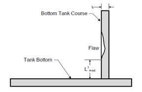
In contrast, a limitation of API 579 relates to the current guidance for permissible spacing to major structural discontinuities, Lmsd. Many of the thinning assessment techniques in API 579 are only applicable to regions of the tank shell a minimum of Lmsd = 1.8√Dtc from a discontinuity such as the bottom corner joint, where D is the tank diameter and tc is the corroded thickness. This API 579 spacing criterion virtually eliminates the availability of some closed-form Level 1 and Level 2 FFS methods for local thinning on the lowest shell course of large-diameter ASTs given the proximity to the bottom corner joint. As a result, a Level 3 assessment would be required per API 579 to assess damage failing the Lmsd criterion. Note, however, that a Level 3 stress analysis in the critical zone near the bottom corner joint would certainly be warranted if the local thinning is in fact extended near that region because the corner joint does not have a defined code equation or design procedure. Overall, the Lmsd criterion is much more fitting for pressure vessels and is currently earmarked as an item for improvement in future releases of API 579 due to the perceived conservatism for large-diameter ASTs.
Case Study – Level 3 Localized Thinning of Corner Joint
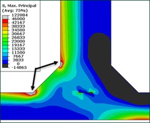
Inspection was performed on a 245-foot-diameter (74.6 m), carbon-steel, internal floating roof AST in crude service, and a region of local metal loss was identified on the tank bottom and shell in proximity to the corner joint. Given the location of the damage, a Level 3 assessment in accordance with API 579 was required to assesses the localized thinning; API 653 does not offer rules for localized thinning across this junction. For reference, had this region of local thinning been identified exclusively on the shell near the top of the first course, the API 579 Level 3 assessment would still have been required based on the current discontinuity spacing criterion Lmsd, but the API 653 evaluation methods could have been applied.
A grid of ultrasonic thickness data was provided to characterize the thinning on the shell and bottom. These minimum measured thicknesses were applied to the FEA model and analyzed per the techniques in API 579 Part 5 and Annex 2D. Results of the evaluation indicated that a reduced fill height of about 75% full was necessary to satisfy the required load cases using a future corrosion allowance (FCA) representing 10 years of remaining life. The derated fill height of 75% was not acceptable for tank operations, so a reduced FCA was investigated to qualify an allowable fill height of 85% full. The reduced FCA correlates to a remaining life of 1-2 years, at which point an outage was scheduled for repairs. This study showcases the benefit of FFS to support continued service and optimize remaining life.
Brittle Fracture
In the case of shell distortions, we have seen that API 653 does not include evaluation techniques, yet evaluation methodology is provided for local metal loss as well as references indicating that API 579 may be used as an alternative means of evaluation. With regard to brittle fracture, API 653 includes a mix of these two ideas. Paragraph 4.3.6 of API 653 refers to flaws such as cracks and laminations with no specific reference to evaluation, thus leaving the door open for the use of API 579 Part 9 “Assessment of Crack-Like Flaws.” Further along in Section 5 of API 653, brittle fracture assessment is detailed in a step-by-step procedure where Step 9 permits the use of alternative analysis to determine risk for brittle fracture. Thus, not only can Part 9 of API 579 be used if crack-like flaws are detected, but this methodology can also be used to perform a detailed brittle fracture assessment in lieu of the guidance provided in API 653.
One last topic relating to brittle fracture is that of hydrostatic testing exemption. Hydrostatic testing is required upon initial construction and following any major repairs or alterations. In some instances, this testing is not practical; therefore, API 653 provides alternative requirements for exemption. One such requirement is an FFS evaluation performed by an experienced storage tank engineer. This evaluation typically consists of the engineer determining permissible flaw sizes for critical repair locations and inspection being carried out to ensure crack-like flaws are not found, thus protecting against the risk of fracture for any newly installed welds.
Case Study – Level 3 Brittle Fracture Assessment
An engineering assessment was performed on a 212-foot-diameter (64.6 m) open-roof AST to evaluate the possibility to exempt the AST from hydrostatic testing following major repairs to the lower shell and annular plate within the critical zone. In addition to a thorough review of the repair plan, API 579 Part 9 and Annex 2D were used to guide the evaluation of risk for brittle fracture. An elastic FEA was created of the repaired tank geometry, and a fracture mechanics study was performed to determine permissible flaw sizes for the corner joint and lower shell. The permissible flaw sizes were then used as an inspection screening tool for examination of the repair welds in these regions. Although small in size, the calculated permissible flaw sizes were determined to be at detectable thresholds using the modern inspection methods employed. A comprehensive inspection was performed and no crack-like flaws were identified; therefore, the AST was exempted from hydrostatic testing as brittle fracture would not be anticipated upon return to service.
Conclusions
Overall, we find that it is critical to pair API 579 with API 653 to get the most out of FFS assessment of ASTs. The application of API 579 is not limited to the damage discussed herein but can also be extended to other flaw types to fill the gaps in API 653 or other in-service codes. When the technology and applicability of API 579 is fully understood, FFS assessment is found to be an integral tool in the life-cycle management of ASTs.
For more information on our FFS-related services for storage tanks, submit the contact form below: